Current in a series circuit is the same through all components. It is calculated using Ohm’s Law: I = V/R.
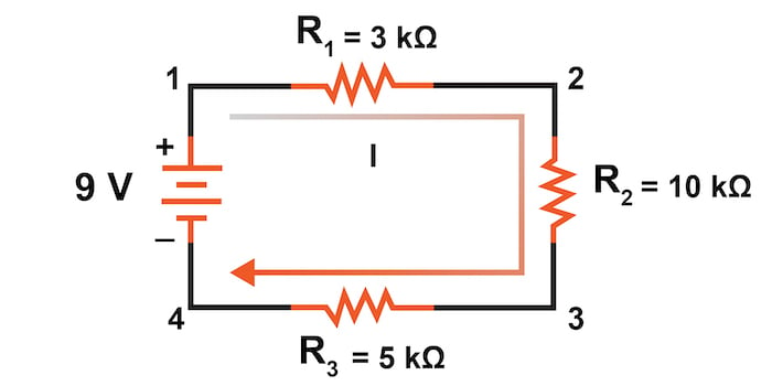
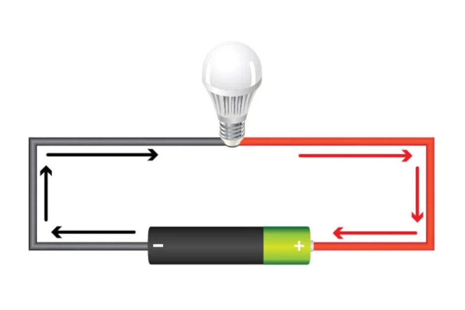
A series circuit is a simple electrical circuit in which components are connected end-to-end, forming a single path for current flow. In this configuration, the current remains constant through each component. Voltage, however, drops across each component based on its resistance.
Using Ohm’s Law, you can determine the current by dividing the total voltage by the total resistance. This principle makes series circuits easy to analyze and useful in various applications, from simple household electronics to complex industrial systems. Understanding how to calculate current in a series circuit is essential for anyone working with electrical systems.
Credit: www.allaboutcircuits.com
Introduction To Series Circuits
Understanding series circuits is crucial in electronics. They are simple yet foundational. Let’s dive into what series circuits are and why they matter.
Definition Of Series Circuits
A series circuit has components connected end-to-end. The current flows through each component one after another. If one component fails, the entire circuit stops working. This is a key characteristic.
Here is a basic representation of a series circuit:
[Power Source] -- [Component 1] -- [Component 2] -- [Component 3]
Importance Of Series Circuits
Series circuits are important in various applications. They are simple to design and understand. You can find them in Christmas lights and old-fashioned radios.
One main benefit is the consistent current throughout the circuit. This makes them predictable and easy to calculate.
Here is a quick overview of their benefits:
- Easy to design and build
- Consistent current through all components
- Useful in basic electronic projects
- Simple troubleshooting
Basic Components
Understanding the basic components of a series circuit is essential. This knowledge helps in calculating the current effectively. Every series circuit has key parts. These include resistors and voltage sources.
Resistors
Resistors control the current flow in a circuit. They are vital for protecting other components. Resistors are measured in ohms (Ω). Their value affects the total resistance in the circuit.
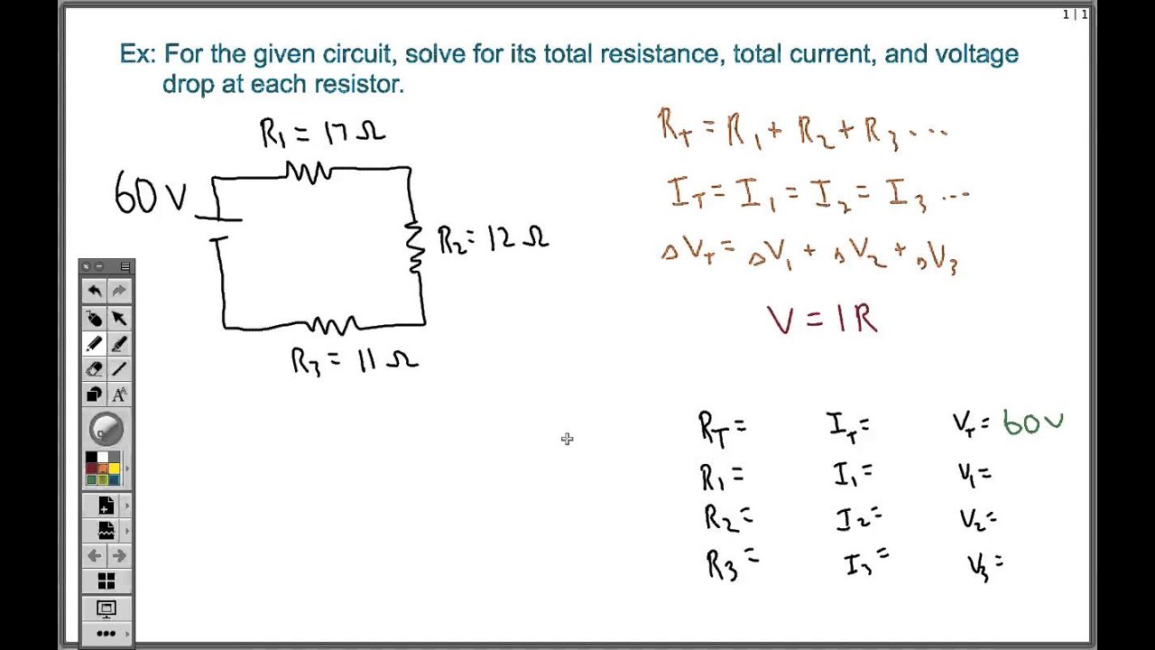
In a series circuit, the total resistance is the sum of all resistors. For example:
R_total = R1 + R2 + R3
If you have three resistors with values 2Ω, 3Ω, and 5Ω, the total resistance is:
R_total = 2Ω + 3Ω + 5Ω = 10Ω
Voltage Sources
Voltage sources provide the energy needed for the circuit. They are measured in volts (V). Common examples are batteries and power supplies.
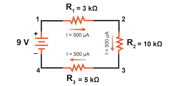
In a series circuit, the voltage from the source is shared across all components. If the voltage source is 12V and there are three resistors, each resistor gets a portion of the 12V.
Here’s a simple table to understand the distribution:
| Component | Voltage (V) |
|---|---|
| Resistor 1 (2Ω) | 4V |
| Resistor 2 (3Ω) | 4V |
| Resistor 3 (5Ω) | 4V |
The total voltage is always the sum of the individual voltages across each resistor. This is a key principle in series circuits.
Ohm’s Law Essentials
Understanding Ohm’s Law is key to mastering current calculation in series circuits. It states that the current through a conductor is directly proportional to the voltage across it and inversely proportional to its resistance.
Formula And Units
Ohm’s Law is represented by the formula:
I = V / RWhere:
- I is the current in amperes (A)
- V is the voltage in volts (V)
- R is the resistance in ohms (Ω)
This formula helps calculate the current in a series circuit. Current is measured in amperes. Voltage is measured in volts. Resistance is measured in ohms.
Application In Series Circuits
In a series circuit, the current is the same at every point. Use Ohm’s Law to find the current in the circuit. Sum the resistances to find the total resistance.
For example, consider a series circuit with three resistors:
| Resistor | Resistance (Ω) |
|---|---|
| R1 | 10 |
| R2 | 20 |
| R3 | 30 |
The total resistance (Rtotal) is:
Rtotal = R1 + R2 + R3 = 10 + 20 + 30 = 60 ΩAssume the voltage (V) is 120V. Using Ohm’s Law:
I = V / Rtotal = 120V / 60Ω = 2ASo, the current (I) is 2 amperes.
This simple calculation shows how Ohm’s Law applies to series circuits.
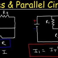
Credit: m.youtube.com
Calculating Total Resistance
Understanding how to calculate total resistance in a series circuit is crucial. It helps in analyzing and designing electrical circuits effectively. In a series circuit, resistors are connected end-to-end, making the current flow through each resistor sequentially.
Sum Of Resistances
In a series circuit, the total resistance (Rtotal) is the sum of all individual resistances. This means you simply add up each resistor’s value. The formula is straightforward:
Rtotal = R1 + R2 + R3 + ... + RnHere’s a simple example:
- If you have three resistors, R1 = 2Ω, R2 = 3Ω, and R3 = 5Ω.
- The total resistance would be: Rtotal = 2Ω + 3Ω + 5Ω = 10Ω
Examples And Practice Problems
Let’s dive into some examples and practice problems to reinforce the concept.
| Resistor Values (Ω) | Total Resistance (Ω) |
|---|---|
| 1Ω, 2Ω, 3Ω | 6Ω |
| 4Ω, 5Ω | 9Ω |
| 10Ω, 20Ω, 30Ω | 60Ω |
Try solving these practice problems:
- Find the total resistance for R1 = 7Ω, R2 = 8Ω, and R3 = 15Ω.
- Calculate the total resistance for R1 = 1Ω, R2 = 2Ω, R3 = 3Ω, and R4 = 4Ω.
- Determine the total resistance for R1 = 6Ω and R2 = 9Ω.
By mastering these basic calculations, you can handle complex circuits with ease. Always remember, in a series circuit, resistances simply add up.
Voltage Drop Across Components
Understanding the voltage drop across components in a series circuit is crucial. Each component in the circuit affects the overall voltage. This section will break down the concept and calculation of voltage drops.
Concept Of Voltage Drop
The voltage drop is the reduction in voltage as electric current passes through a component. In a series circuit, the sum of all voltage drops equals the total supply voltage. This is because the current has only one path to follow.
Each component’s resistance causes a drop in voltage. The higher the resistance, the larger the voltage drop. Understanding this concept helps in designing efficient circuits.
Calculating Voltage Drops
To calculate the voltage drop across each component, use Ohm’s Law: V = I R.
| Component | Resistance (Ω) | Current (A) | Voltage Drop (V) |
|---|---|---|---|
| Resistor 1 | 10 | 2 | 20 |
| Resistor 2 | 20 | 2 | 40 |
| Resistor 3 | 30 | 2 | 60 |
The total voltage drop is the sum of individual drops. This should match the supply voltage. If the supply voltage is 120V, the sum of 20V, 40V, and 60V equals 120V.
- Identify the resistance of each component.
- Measure the current flowing through the circuit.
- Apply Ohm’s Law to find voltage drops.
- Calculate voltage drop for Resistor 1:
V1 = I R1 = 2A 10Ω = 20V. - Calculate voltage drop for Resistor 2:
V2 = I R2 = 2A 20Ω = 40V. - Calculate voltage drop for Resistor 3:
V3 = I R3 = 2A 30Ω = 60V.
By understanding these steps, you can predict and control voltage drops. This ensures that each component receives the correct voltage.
Current Calculation Method
Calculating the current in a series circuit is essential for understanding how electrical components function. This method helps in determining how much current flows through each component. By using fundamental principles, you can easily compute the current in any series circuit.
Using Ohm’s Law
Ohm’s Law is the most important tool for calculating current. The formula is:
I = V / R
Where:
- I is the current in amperes (A).
- V is the voltage in volts (V).
- R is the resistance in ohms (Ω).
In a series circuit, the total resistance is the sum of individual resistances. Use this total resistance in the formula to find the current.
Step-by-step Guide
Follow these steps to calculate the current:
- Identify the total voltage of the circuit.
- Determine the resistance of each component.
- Add up all the resistances to get the total resistance.
- Apply Ohm’s Law using the total voltage and total resistance.
Let’s consider an example:
| Component | Resistance (Ω) |
|---|---|
| Resistor 1 | 10 |
| Resistor 2 | 20 |
| Resistor 3 | 30 |
Total resistance = 10Ω + 20Ω + 30Ω = 60Ω
If the total voltage is 120V, then using Ohm’s Law:
I = 120V / 60Ω = 2A
The current flowing through the circuit is 2 amperes.
Practical Applications
Understanding current calculation in a series circuit is vital in many real-world scenarios. This knowledge helps in designing and troubleshooting various electrical systems.
Real-world Examples
Series circuits are used in many everyday devices and systems. Here are a few real-world examples:
- Christmas Lights: If one bulb fails, the entire string goes out.
- Old Flashlights: Batteries are connected in series to increase voltage.
- Decorative Lights: Series circuits are common in simple light setups.
Troubleshooting Tips
Knowing how to calculate current in a series circuit can help in troubleshooting. Here are some tips:
- Check Each Component: Ensure all components are working correctly.
- Measure Current: Use a multimeter to measure the current at different points.
- Inspect Connections: Look for loose or corroded connections.
- Replace Faulty Parts: Swap out any defective components in the series.
Credit: www.allaboutcircuits.com
Common Mistakes
Calculating current in a series circuit can be tricky. Many people make mistakes that affect the results. Learning these common errors helps you avoid them.
Avoiding Calculation Errors
One common mistake is not using the correct formula. In a series circuit, the current is the same through all components. Use Ohm’s Law: I = V / R.
Another mistake is incorrectly adding resistances. In a series circuit, add all resistances to find the total resistance. Use this formula: Rtotal = R1 + R2 + R3 + ...
Incorrectly reading values from the multimeter can also lead to errors. Always double-check the multimeter settings and readings.
Misunderstanding Voltage Drops
Some people misunderstand voltage drops in a series circuit. The total voltage is the sum of the individual voltage drops across each component.
Use this formula to find voltage drops: Vdrop = I x R. Calculate the voltage drop across each resistor separately.
Always ensure that the sum of the voltage drops equals the total voltage of the power source. This confirms accurate calculations.
Advanced Topics
Understanding current calculation in a series circuit can be straightforward. Yet, delving into advanced topics is essential for a deeper grasp. This section explores the impact of power rating and the combination of series and parallel circuits.
Impact Of Power Rating
Power rating is crucial in series circuits. Each component has a specific power rating. Exceeding this rating can damage the component.
Let’s look at a table to understand better:
| Component | Power Rating (W) | Voltage (V) | Current (I) |
|---|---|---|---|
| Resistor A | 0.5 | 5 | 0.1 |
| Resistor B | 1 | 10 | 0.1 |
In a series circuit, the current remains the same. But the voltage across each component varies. Ensure each component’s voltage does not exceed its rating.
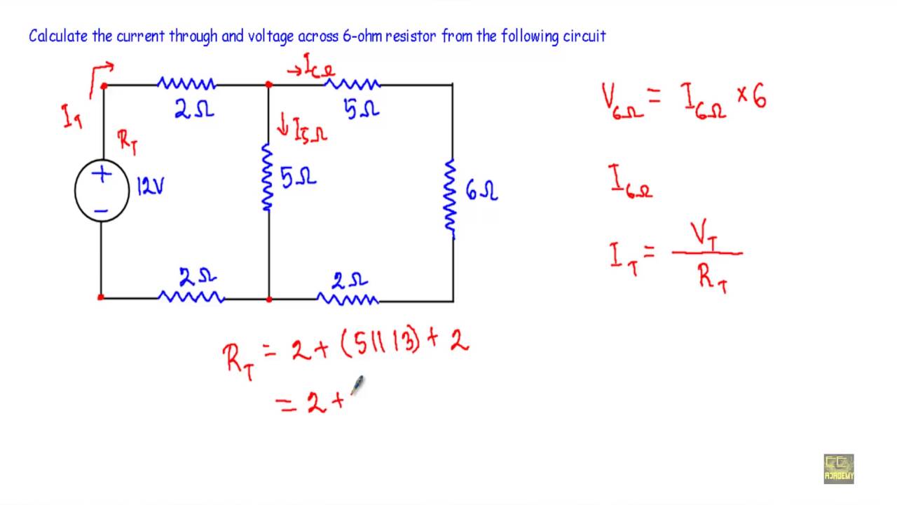
Combining Series And Parallel Circuits
Series and parallel circuits can be combined. This combination helps in managing current and voltage distribution.
Here are some key points:
- Series circuits have a single path for current.
- Parallel circuits have multiple paths for current.
- Combining both can optimize power usage.
Consider a circuit with two resistors in series connected to a parallel branch. The current flows through each branch differently. This combination allows better control over the circuit’s power distribution.
Here is a simple code example:
# Calculate total resistance in a combined circuit
R1 = 5  # Resistor in series
R2 = 10 # Resistor in parallel branch 1
R3 = 15 # Resistor in parallel branch 2

total_parallel_resistance = 1 / (1/R2 + 1/R3)
total_resistance = R1 + total_parallel_resistance

print(total_resistance)
Understanding these advanced topics helps in designing efficient circuits. It ensures components operate within their limits, enhancing the circuit’s longevity and reliability.
Frequently Asked Questions
What Is A Series Circuit?
A series circuit is an electrical circuit where components are connected end-to-end. This means that current flows through each component sequentially without branching.
How To Calculate Current In A Series Circuit?
To calculate current in a series circuit, use Ohm’s Law: I = V / R. Sum the resistances and divide the voltage by the total resistance.
Why Does Current Stay Constant In Series Circuits?
Current stays constant in series circuits because there is only one path for electron flow. Each component receives the same current.
What Happens If One Component Fails?
If one component fails in a series circuit, the entire circuit is interrupted. Current stops flowing through all components.
Conclusion
Understanding current calculation in a series circuit is essential for electrical projects. It helps in designing safe circuits. Remember, the current remains constant throughout the series circuit. Accurate calculations ensure efficiency and safety. Mastering these basics will enhance your electrical skills and project success.
Keep practicing to become proficient.
You can also read: Resistor Calculation in Series


1 thought on “Current Calculation in a Series Circuit: Mastering the Basics”