Inductance is the property of an electrical conductor that opposes changes in current. It is measured in henries (H).
Inductance plays a crucial role in electrical circuits. It helps manage the flow of current and stores energy in magnetic fields. Engineers use inductors, components designed to introduce inductance, in various applications. These include transformers, motors, and filters in electronic devices.
Understanding inductance is essential for designing efficient and functional electrical systems. Inductance can impact circuit performance, influencing both energy storage and signal processing. It is critical for developing technologies like wireless communication and power supply systems. By grasping the concept of inductance, one can better appreciate its significance in modern electronics and electrical engineering.
Introduction To Inductance
Inductance is a fundamental concept in electronics. It plays a crucial role in the functioning of many devices. Understanding inductance can help you grasp how circuits work.
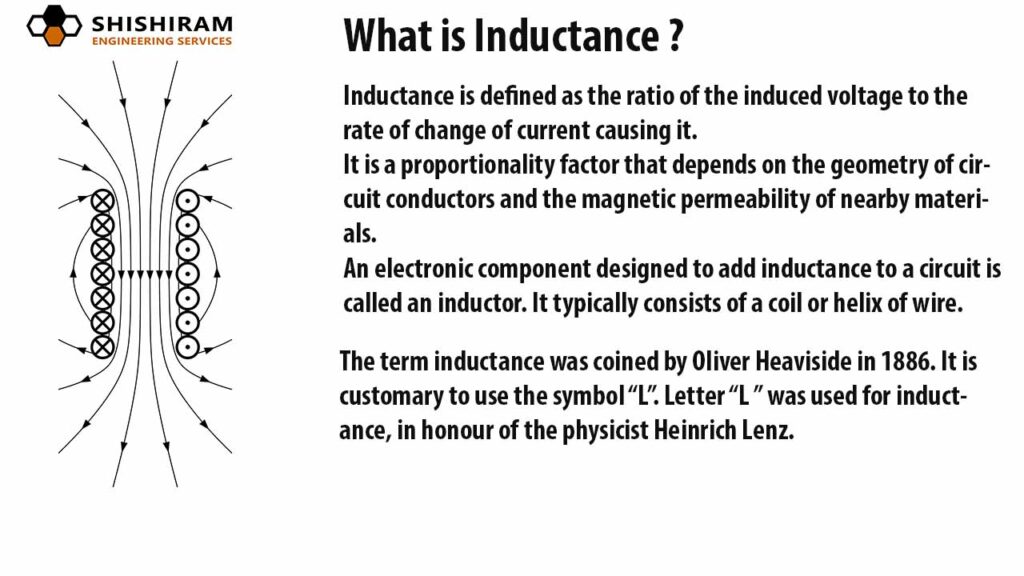
What Is Inductance?
Inductance is the property of a conductor. It opposes changes in current. It is measured in Henrys (H).
Think of inductance like inertia in physics. Just as a mass resists changes in motion, inductance resists changes in electric current. A coil of wire is a common example.
Here’s a simple formula for inductance:
L = (N² μ A) / l- L is the inductance.
- N is the number of turns in the coil.
- μ is the permeability of the core material.
- A is the cross-sectional area of the coil.
- l is the length of the coil.
Importance In Electronics
Inductance is vital in many electronic applications. It is used in transformers, inductors, and motors. It can store energy in magnetic fields.
Here are some key roles:
- Energy Storage: Inductors store energy in magnetic fields.
- Filtering: Inductors filter signals in circuits.
- Voltage Regulation: Inductors help stabilize voltage in power supplies.
Understanding inductance can help you design better circuits. It can also help you troubleshoot electronic problems.
| Application | Role of Inductance |
|---|---|
| Transformers | Transfers energy between circuits |
| Motors | Converts electrical energy to mechanical |
| Filters | Removes unwanted signals |
Basic Principles
Inductance is a key concept in electronics. It refers to the ability of a coil to store energy in a magnetic field. Understanding inductance is essential for working with circuits. Let’s dive into the basic principles.
Magnetic Fields
Magnetic fields are created by moving electric charges. A wire carrying current produces a magnetic field around it. This field is circular and perpendicular to the wire. The strength of the field depends on the current and the distance from the wire.
Coiling the wire increases the magnetic field. More coils mean a stronger field. Coils are often wrapped around a core to concentrate the field. This setup is called an inductor.
Faraday’s Law
Faraday’s Law states that a changing magnetic field induces an electromotive force (EMF). This EMF generates a current in a closed circuit. The induced EMF is proportional to the rate of change of the magnetic field.
Mathematically, Faraday’s Law is expressed as:
EMF = -N (dΦ/dt)
Where:
- EMF: Induced electromotive force
- N: Number of turns in the coil
- dΦ/dt: Rate of change of magnetic flux
This principle is crucial in transformers, inductors, and many other electrical devices.
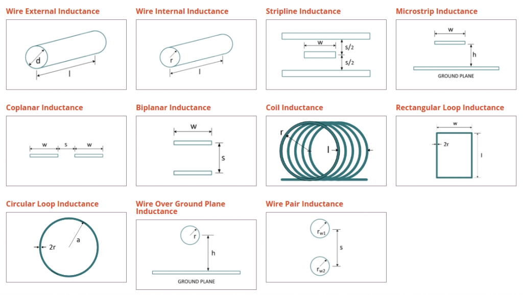
Types Of Inductors
Inductors are key components in many electronic devices. They store energy in a magnetic field. Understanding the different types of inductors helps in selecting the right one for any application.
Air Core Inductors
Air Core Inductors do not use any magnetic material. They have a coil wound around a non-magnetic core, such as plastic or ceramic. These inductors are ideal for high-frequency applications.
- No core material – just air or non-magnetic material.
- High Q factor – suitable for RF circuits.
- Low inductance values – often used in filters and oscillators.
Iron Core Inductors
Iron Core Inductors use an iron core to increase inductance. The iron core enhances the magnetic field strength, making these inductors efficient at lower frequencies.
- Iron core – boosts magnetic field strength.
- High inductance values – suitable for power supplies.
- Low-frequency applications – used in transformers and chokes.
Ferrite Core Inductors
Ferrite Core Inductors have a core made of ferrite material. Ferrite is a ceramic compound with magnetic properties. These inductors are widely used in a variety of applications.
- Ferrite core – offers high permeability.
- Wide frequency range – used in power and RF circuits.
- Efficient energy storage – common in filters and transformers.
Credit: medium.com
Inductance In Circuits
Inductance plays a crucial role in electrical circuits. It affects how circuits respond to changing currents. Understanding inductance helps in designing effective and efficient circuits. Let’s explore how inductance works in different circuit configurations.
Series And Parallel Inductors
Inductors can be connected in series or parallel. Each configuration affects the total inductance differently. In a series connection, the total inductance is the sum of all individual inductances.
For example:
Ltotal = L1 + L2 + L3 + ...Parallel inductors have a different formula. The total inductance is given by the reciprocal of the sum of reciprocals of individual inductances.
1/Ltotal = 1/L1 + 1/L2 + 1/L3 + ...Here’s a comparison table:
| Configuration | Total Inductance Formula |
|---|---|
| Series | Ltotal = L1 + L2 + L3 + … |
| Parallel | 1/Ltotal = 1/L1 + 1/L2 + 1/L3 + … |
Lc Circuits
LC circuits consist of an inductor (L) and a capacitor (C). These circuits are used for tuning and filtering applications. They can resonate at a specific frequency.
The resonant frequency (f0) is given by:
f0 = 1 / (2π√(LC))At this frequency, the inductive reactance equals the capacitive reactance. This results in a minimal impedance, allowing maximum current flow.
LC circuits are essential in radio transmitters, receivers, and various electronic filters.
Rl Circuits
RL circuits include a resistor (R) and an inductor (L). They are used for filtering and timing applications. The time constant (τ) of an RL circuit is given by:
τ = L / RThe time constant indicates how quickly the current reaches its steady state. A larger inductance or smaller resistance results in a slower response.
RL circuits are found in power supplies and signal processing applications.
These circuits can also smooth out rapid changes in current, protecting sensitive components.
Measuring Inductance
Measuring inductance is crucial for many electronic applications. Knowing how to measure inductance accurately helps in designing circuits and troubleshooting issues. Below are some common methods used for measuring inductance.
Lcr Meters
LCR meters are specialized tools for measuring inductance, capacitance, and resistance. They provide accurate and quick readings.
- Accuracy: LCR meters offer high precision.
- Ease of Use: Simple to operate with minimal training.
- Versatility: Can measure multiple parameters, not just inductance.
To measure inductance using an LCR meter:
- Connect the inductor to the meter’s terminals.
- Select the inductance measurement mode.
- Read the inductance value displayed on the screen.
Oscilloscope Methods
Oscilloscopes can also measure inductance, although they are primarily used for viewing waveforms. This method is more complex but useful in advanced applications.
Two common oscilloscope methods include:
| Method | Steps |
|---|---|
| Step Response Method |
|
| Resonant Frequency Method |
|
While oscilloscopes require more setup, they offer valuable insights into inductor behavior.

Credit: m.youtube.com
Applications In Electronics
Inductance plays a vital role in many electronic devices. It helps in transforming voltage levels, filtering signals, and storing energy. Let’s explore some key applications.
Transformers
Transformers use inductance to transfer electrical energy between circuits. They can step up or step down voltage levels. This is essential for power distribution.
| Type | Application |
|---|---|
| Step-up Transformer | Increases voltage for long-distance power transmission |
| Step-down Transformer | Decreases voltage for safe home use |
Filters
Filters use inductance to clean up electrical signals. They block unwanted frequencies and allow desired ones. This is crucial in audio and communication systems.
- Low-pass filters allow low frequencies to pass.
- High-pass filters allow high frequencies to pass.
- Band-pass filters allow a range of frequencies to pass.
Energy Storage
Inductors can store energy in a magnetic field. This energy storage is temporary but useful. It helps in maintaining power supply in various devices.
- Inductors in power supplies smooth out voltage spikes.
- They help in DC-DC converters for stable power output.
- Inductors are essential in RF and microwave circuits.
Challenges And Limitations
Inductance plays a crucial role in electronic circuits. Yet, it comes with various challenges and limitations. Understanding these can help improve circuit design and performance.
Parasitic Inductance
Parasitic inductance refers to unintended inductance in a circuit. It arises from the layout and components used.
- Parasitic inductance can cause signal distortion.
- It leads to unwanted oscillations.
- It affects high-frequency circuits the most.
Reducing parasitic inductance involves careful PCB design. Use shorter traces and proper grounding techniques. High-frequency applications need special attention.
Core Saturation
Core saturation occurs when the magnetic core of an inductor reaches its limit. At this point, the core cannot store more energy.
- Core saturation leads to reduced inductance.
- It causes overheating of the core.
- It can damage the inductor and circuit.
Avoid core saturation by choosing the right core material. Ensure the core operates within its limits. Proper design prevents core saturation.
Understanding these challenges ensures better performance and reliability in electronic circuits.
Future Trends
The world of inductance is evolving rapidly. Innovations promise to reshape how we use inductors. This section explores future trends in this field.
Advances In Materials
New materials are making inductors better. Nanomaterials offer higher efficiency and smaller sizes. These materials reduce energy loss and improve performance.
Here is a comparison of traditional and new materials:
| Material Type | Efficiency | Size | Cost |
|---|---|---|---|
| Traditional Ferrites | Moderate | Large | Low |
| Nanomaterials | High | Small | Medium |
Miniaturization
Miniaturization is a key trend. Smaller inductors fit in tiny spaces. This is crucial for modern gadgets. Wearable tech and smart devices benefit the most.
Benefits of miniaturization include:
- More compact designs
- Better energy efficiency
- Increased portability
3D printing helps create tiny inductors. This technology makes production faster and cheaper. The future of inductance looks bright with these advancements.

Credit: www.youtube.com
Frequently Asked Questions
What Is Inductance?
Inductance is a property of an electrical conductor. It opposes changes in current flow. It’s measured in Henrys (H).
How Does Inductance Work?
Inductance works by generating an opposing voltage. This happens when the current through a coil changes. It creates a magnetic field.
Why Is Inductance Important?
Inductance is crucial in electronic circuits. It helps in filtering signals, storing energy, and in transformers. It ensures proper functioning.
What Affects Inductance In A Coil?
Several factors affect inductance. These include the number of turns, coil area, and core material. Wire length and spacing also matter.
Conclusion
Understanding inductance is crucial for modern electronics and electrical systems. It impacts circuit design and functionality. By mastering this concept, engineers can create efficient and reliable devices. Keep exploring and learning about inductance to stay ahead in the field. Your knowledge will drive innovation and technological advancements.